
Maneuvering effects
- Andreas
- Aug 26, 2020
- 5 min read

Updated: Aug 27, 2020
When an aircraft performs turns, pull-up’s or push-over’s, many things are different from the “straight-and-level” regime. Engineers worry about that a lot and pilots can take away some important insights from those considerations. Here are some practical questions to get started:
What is the difference (in terms of stability):
- between a 2 g wings-level pull-up and a 2 g level turn?
- when flying a 2 g level turn at sea-level and doing the same at high altitude?

Figure 1: Formation maneuvering (the gentleman top left is still practicing)
Maneuvering stability
This kind of stability analysis takes into account the geometrical effects of an aircraft subject to an angular rate, sometimes referred to as “accelerated flight” [1] [2]. Basic flight mechanics dictate, that the conventional aircraft performs most of the accelerated flight by generating a pitch rate and thus, longitudinal maneuvering stability is by far the most important consideration [1]. It is not surprising, that many people automatically link the term maneuvering stability to “stick-force per g”, or how hard a pilot needs to pull on the stick to create a certain g-load, as this is a direct consequence of the aircraft’s maneuvering stability properties [2]. The goal of the aircraft manufacturer is always to find a good compromise between agility and making sure the pilot will not inadvertently overstress the airframe. It is quite obvious that a fighter will have a completely different maneuver envelope than a civil transport aircraft.
The key to understand maneuvering stability: Tailplane AOA
When an aircraft is subject to a pitch-rate, the tailplane is exposed to a different AOA than without the pitch-rate. This becomes obvious when studying Figure 2. Additional lift is created at the tailplane, causing an opposing pitching moment (ΔM) and thus damping the pitch-rate [3]. The damping moment is proportional to pitch rate (Q) and the distance of the tailplane from the CG (tail arm, lt) [1][3]. Note that the contribution of increased wing-downwash is neglected for this basic analysis, as it is rather small.
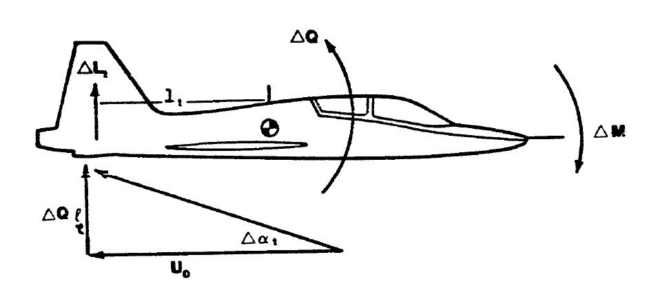
Figure 2: Pitch-damping due to pitch-rate [3]
The pitch damping is directly affected by TAS (Uo). As TAS increases, the change in tailplane AOA reduces, and thus the damping is less. This fact is crucial and leads to the following key points for pilots:
- Maneuvering stability depends on altitude. When climbing at constant EAS, the aircraft will become more sensitive to control inputs as altitude increases.
- If the aircraft is experiencing an undesired oscillation (e.g.: dutch-roll), it might be worth descending and slowing down in order to reduce the TAS and thereby increasing the damping factor.
Stick-force per g
As mentioned earlier, the “stick-force per g” is a crucial parameter. Some limits are given by the airworthiness certification requirements [2] but in the civil world, much is left at the manufacturer’s discretion. Traditionally, military standards have been much more detailed on control forces for maneuvering for obvious reasons [2]. The following list provides a summary of the effects on the stick-force per g [1][2][4]:
Altitude
As depicted in Figure 2, increased TAS decreases the pitch damping and thus decreases the stick-force per g when climbing at constant EAS.
Wing loading
High wing-loading (aircraft mass divided by wing area) tends to increase the stick-force per g. A general statement is not possible, as the effect is influenced by several factors.
Tail arm
The longer the tail arm, the more pronounced the pitch-damping, thus the higher the stick-force per g. This is one of the reasons that fighters typically have a rather short tail arm but large tail surface.
CG position
Moving the CG forward effectively increases the tail arm and therefore increases the stick-force per g.
Speed (without Mach effect)
This may be surprising: When maintaining altitude and simply changing the speed, the “slope” of the stick-force per g graph does not change. It is simply offset up or down (see “offset” comment in Figure 3). This is caused by the fact that the increased aerodynamic force on the control surface (and thus the stick) is compensated by the smaller surface displacement needed per g.
Mach number
Compressibility at high Mach numbers tends to increase the stick-force per g.
Pull-up vs. turn
Back to the question at the beginning: How come, 2 g is not the same as 2 g? As explained in Figure 2, pitch-damping is depending on the pitch-rate. It can be demonstrated by basic flight mechanics, that the pitch-rate for a given load factor is higher in a level turn than in a pull-up [1][2]. For the level turn pitch-rate is related to n-1/n, whereas in the pull-up it is related to n-1 [2]. The higher pitch-rate in the level turn causes more pitch-damping, and therefore a higher stick-force. See the different lines (amber/blue) in Figure 3.
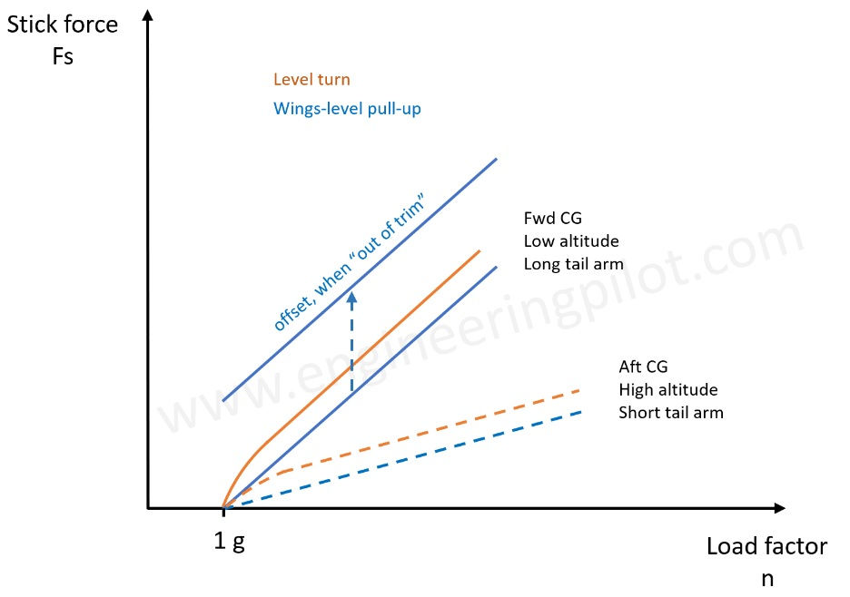
Figure 3: Stick-force per g for level turn and pull-up at different conditions
As pitch-damping is opposite to the prevailing pitch rate, the aircraft is generally more stable during maneuvering flight than in straight and level flight [1][2].There are limitations however, similar to the allowable CG positions for static considerations.
Reminder: An aircraft’s neutral point (NP)
In static longitudinal stability, there is a CG location, where the restoring pitching moment after a disturbance becomes zero (the aircraft is said to be “neutrally stable”) at this point. (See article cm-alpha). In fact, there are two neutral points, one “stick-free”, the other one “stick-fixed” whereas the stick-fixed NP is always further aft than the stick-free. The difference is simply that for the stick-free NP, the elevator is allowed to “float” [1][4].
The maneuvering point (MP)
Equivalent CG positions can be determined for maneuvering flight: There is a CG location, where the aircraft will maintain a different load factor after a disturbance. Again, this exists for both, stick-free and stick-fixed [2] [3]. For the mathematically inclined, the stick-free maneuvering point is the CG location, where the partial derivative of the stick-force with respect to load factor becomes zero. Likewise, the stick-fixed maneuvering point is the CG location, where the partial derivative of the stick-position with respect to load factor becomes zero. Figure 4 below provides a comprehensive summary of the four CG locations just discussed:
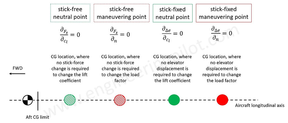
Figure 4: Summary of neutral and maneuvering points with definitions
It is self-explanatory that these CG positions are of a theoretical nature for conventional aircraft. (As it would be extremely hazardous to operate a conventional aircraft in those regions). With the advent of sophisticated digital flight control systems that allow closed-loop control of highly unstable systems and given the advantages in maneuvering capability, it is not surprising that combat aircraft designs tend to involve solutions that are no longer controllable by a human being.
Revision/20200827
References
[1] M. V. Cook, “Flight dynamics principles”, 2nd edition, Butterworth-Heinemann
[2] B. Crawford, “Unusual Attitudes and the Aerodynamics of Maneuvering Flight”, 2009
[3] USAF Test pilot school, “Flying qualities phase”, vol 2, 1990
[4] P.J. Swatton, “The principles of flight for pilots”, 2011, Wiley


