
Weather radar evolution: from tilt management to GNSS interference
- Andreas
- Aug 17, 2025
- 4 min read

Updated: Aug 18, 2025
With legacy weather radar systems, the flight crew was significantly involved in the actual control of the radar beam. This required considerable skill and provided plenty of opportunities to “get it wrong”. Modern systems require less crew involvement in the data collection process but instead offer a large data buffer from which the crew can select a region they wish to monitor. This has significantly reduced workload but inevitably also caused skill fading when it comes to “tilt-management”. A key-point is this:
No matter how modern the system, basic physical limits still apply.
It is therefore necessary to have some understanding of weather radar beam physics even when using a modern system. This article will omit the basic tilt and gain setting techniques used in older systems, as there is plenty of guidance material available covering that. The interested reader is referred to this article of my friend James Albright.
Beam width: What is it exactly?
Many drawings suggest a rather narrow beam with sharp edges. In reality, the radar beam is a result of antenna physics and the effort to focus most of the RF energy in one direction. The power-density is highest in the center and gradually reduces when moving outwards from the center. The most common definition of beam width is the so-called Half-Power Beam Width (HPBW), or the 3 dB beam width. It refers to the boundary, where the power level has dropped to 50% of the center (boresight) power level. This metric is also used in RTCA Do-220 [1], which governs the technical specifications of airborne weather radar systems.
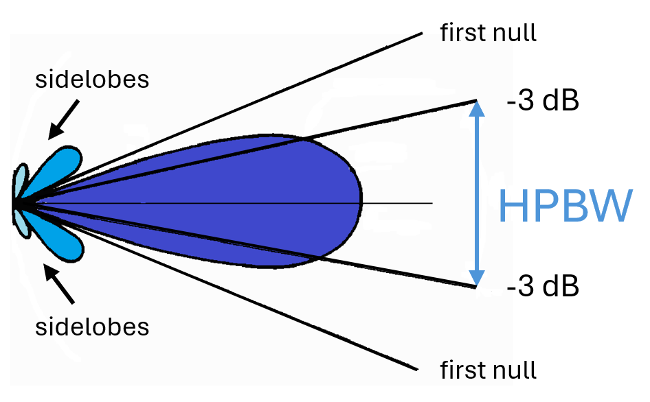
The beam shape is described in RTCA DO-220 [1], covering maximum HPBW and permissible sidelobe power levels.
How narrow can it get?
In antenna physics there is a fundamental relationship between wavelength, antenna dimension (aperture) and achievable beam width [2]. The HPBW is proportional to the ratio of wavelength and antenna aperture [3] [4]:

It is therefore obvious that a larger antenna and a higher frequency (shorter wavelength) will yield a narrower beam. While some legacy airborne weather radar operate in the C-band, most systems nowadays use the X-band. Ground-based weather radars continue to use C-band.
Typical beam width values for X-band radars can be seen below:
Antenna diameter in inch | Antenna diameter in m | HPBW in degrees |
30 | 0.76 | 3.2 |
24 | 0.61 | 4.2 |
18 | 0.46 | 5.6 |
12 | 0.30 | 7.9 |
10 | 0.25 | 10 |
Why is this important? Let us understand just how quickly the vertical resolution deteriorates with lateral scanning distance:

The blue area shows the region covered by a typical 4° HPBW on a flat Earth. It is this area that is most sensitive for weather reflections. The green arrows represent a much greater beam width that is typically sensitive for ground reflections. It becomes apparent that good tilt management requires considerable effort. This is one of many reasons for automatic tilt control and ground clutter suppression as available on today`s products.
Curvature of the Earth
With the tilt angle set to 0°, the beam center will be horizontal (single beam systems). As we can see below, the curvature of the Earth causes the beam’s altitude to diverge rapidly with distance. This is compensated on modern systems where the flight crew can select a flight level to be displayed.

The flight crew can select a flight level, rather than a tilt angle on modern systems. There are also “multi-beam” systems on the market, where the tilt angle set by the crew refers to the average of two beams.
The above illustrations make it clear that applying simple “1:60 rules” without considering beam layout and curvature of the Earth will be quite inaccurate.
Beam pointing error
The accuracy of manual tilt control is further affected by the antenna steering mechanism and the radome. RTCA DO-220 specifies a minimum accuracy for the tilt control, but does not consider the radome, as this will vary from airframe to airframe [1]. A damaged radome (even though it may look fine from outside) can significantly affect the direction and attenuation of the radar beam [2]. See here for a detailed description of the radome.
More inputs, more complexity
Modern weather radar systems have a vast number of additional inputs, such as temperature-controlled gain, GNSS-based ground clutter suppression and even seasonal weather models for certain areas. The flight crew is therefore faced with a potential new set of malfunctions, depending on the product at hand:
Incorrect temperature
Many modern systems use temperature inputs (sometimes based on atmospheric models) to compensate for the lower reflectivity of ice-crystals [5]. A misleading temperature input can therefore affect the displayed weather (over/-under sensitive).
Masked RF-interference
The classical RF-interference pattern on a weather radar screen is depicted in many books: It looks like a spoke (below left). As modern systems use a significant amount of signal processing, this may look rather different on a modern system (below right) [6]:

While it was fairly straight forward to detect interference spokes in the past, it can be a bit more challenging with a modern system. Ideally the signal processing would completely eliminate the effects of the interference, but in reality some traces can remain.
GNSS spoofing
As if there were not enough effects of GNSS-spoofing already, modern weather radars can also be affected. Some manufacturers use GNSS-derived position in conjunction with a terrain database to eliminate ground clutter. While this is certainly superior to conventional ground clutter suppression, it suffers from potential GNSS spoofing effects. In a worst-case scenario, such a weather radar picture may become unreliable due to continuously changing spoofed position information [7].
References
[1] | RTCA, «DO-220A: Minimum Operational Performance Standard for Airborne Weather radar with forward-looking windshear detection...,» RTCA, 2016. |
[2] | W. Melvin und J. Scheer, Principles of modern radar, Edison, NY: Scitech, 2013. |
[3] | R. J. Mailloux, Phased Array Antenna Handbook, Norwood: Artech house, 2005. |
[4] | R. Klemm, Novel Radar Techniques and Applications, Bd. 2, Herts UK: Scitech, 2018. |
[5] | Rockwell Collins, «MultiScan quick reference,» 2010. |
[6] | Honeywell, «IntuVue RDR-7000 Pilot`s guide,» 2020. |
[7] | Ops Group, «GPS Spoofing final report,» 2024. |


